Using Rethink Sawyer Robot Arm to Play Yoyo
Project Description
It is not difficult for humans to play yoyo while it is a challenging problem for robots. The yoyo dynamics are hard to model precisely due to discontinuity, friction, and deformation. Moreover, playing yoyo is a time-critical task that requires the controller to inject energy into the system based on sensor feedback in real-time. This project focuses on developing a ROS software pipeline with hardware experiment for using a robot arm to play yoyo. This project is just one part of a larger research project Teaching a robot to play yoyo from demonstrations. The idea for the visual feedback controller and model mainly comes from the two papers [1] and [2]:
Demo Video:
Simple Yoyo Model
The yoyo parameters are encoded in dimensionless constants
$\eta \doteq \frac{m r^{2}}{I+m r^{2}}$, $\quad \gamma \doteq \frac{\eta}{r}$, $e_{e q}=1-2 \eta$
where $m$ is the mass, $r$ is the axle radius, $I$ is the angular moment of the yoyo, and $e_{e q}$ is the restitution coefficient from [2]
It is important to understand the key movement for yoyo playing. At the time instant when yoyo hits the bottom, the hand or the end-effector should be in an upward motion [1][2]. Therefore, the end-effector needs to start moving upward once the yoyo is below a specific height until the yoyo hits the bottom. We also use the yoyo motion model from [1]
$\ddot{\theta}=-\gamma(g+\ddot{h})$
$y(t)=h(t)-L+r \theta(t), \theta(t)>0$
$\dot{\theta}\left(t_{j}^{+}\right)=-e_{e q} \dot{\theta}\left(t_{j}^{-}\right), \quad \theta\left(t_{j}\right)=0 ; \quad j=1,2, \cdots$
where $\theta(t)$ is the yoyo rotation angle, $y(t)$ is the yoyo position from the ground, $h(t)$ is the end-effector position from the ground, and $L$ is the length of the string.
Control Method
The controller contains a simple switching signal to determine the timing for pulling and return based on the yoyo rotation angle.
$s(t)= \begin{cases}1, & \text { if } \theta<\Theta_{\text {set }} \text { and } \dot{\theta}<0 \\ 0, & \text { else. }\end{cases}$
The following model defines the force for moving the arm for each signal state
$\ddot{h}= \begin{cases}-c_{1} \dot{h}-c_{2} h, & \text { for } s(t)=0 \\ \kappa g, & \text { for } s(t)=1\end{cases}$
where $\kappa > 0$, $c_1 > 0$, and $c_2 > 0$ are the tuning parameters for control
Experiments
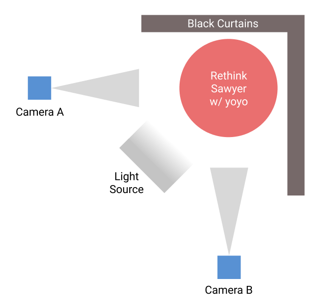
The overall hardware setup consists of two high speed cameras, two black curtains, a lighting source, a Rethink Sawyer robot, and a Duncan Reflex yoyo as shown in Figure below.

Tracking System
AprilTags, a popular choice of visual fiducial tags, are attached on both sides of the yoyo, which are tracked by the two cameras. Although AprilTags are only used for tracking yoyo position and velocity for now, it could potentially be used to capture the yoyo rotation angle in the future.
A fast-moving object usually introduces motion blur with a low-speed camera, which blurs the AprilTags. Therefore, high-speed cameras are needed for keeping track of the AprilTags. Camera A is the EO-0513 USB 3.0 camera from Edmund Optics with a maximum frame rate of 571 FPS. Due to the recent shortage of chips, we were not able to order the second camera with the same model, so instead, we purchased a camera from a different brand with similar specifications. Camera B is the Blackfly S USB3 camera with a maximum frame rate of 522 FPS. Two black curtains are placed behind the robot to reduce background noise when detecting AprilTags. A light source is also used to provide a better and more stable lighting condition for detecting AprilTags.
Different approaches have been tested for tracking yoyo, including (1) Tracking by yoyo color. (2) Tracking by background subtraction (3) Tracking using AprilTags. The yoyo is free to rotate along the string when playing. The shape facing the cameras can change during the rotation, making it hard to find a stable center for color or shape tracking. However, AprilTag also has its own pitfall when used for tracking. It can only be seen when facing the camera within 45 degrees. Therefore, one solution is to attach AprilTags on both sides of the yoyo and place two cameras perpendicular to each other, as shown in Figure 2. This approach ensures that there is always at least one tag being seen by one camera during yoyo playing. The two cameras are running in parallel with a centralized tracking node taking measurements from both cameras. The camera that outputs meaningful measurement is used for the yoyo measured position in the current timestamp.
There are various types of AprilTag families with the trade-off between false-positive rates and tracking distance. The AprilTag family used in this system is “tag25h9”, which contains less bit information for longer distance detection than other families. Since there is no other AprilTag presented in the view, there is no need to worry about the false-positive issue.
Robot Arm Control
One end of the yoyo string is attached to the end effector of the Rethink Sawyer. The Rethink Saywer end-effector can move up and down to apply control to the yoyo. We need to determine the joint action (could be torque or velocity) to produce the desire end-effector motion calculated by the model in the Simple Yoyo Model section. For the current status, we assume that the yoyo only has vertical movement and ignore the horizontal plane movement. To enforce the assumption, the end-effector movement is constrained in a single vertical line. The end-effector is controlled by velocity, so inverse velocity kinematics is needed to calculate the corresponding joint velocity. The joint velocity vector $\dot{\theta}$ can be calculated by
$\dot{\theta}=M^{-1} J^{\mathrm{T}}\left(J M^{-1} J^{\mathrm{T}}\right)^{-1} \mathcal{V}_{d}$
with $M$ being the weight matrix, $J$ being the Jacobian and ${V}_{d}$ being the desired velocities.
Results
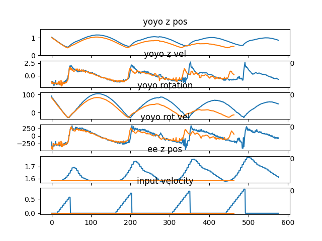
To show that the simple controller can inject energy into the yoyo motion, a comparison was performed with the result shown in Figure 3. The yoyo was released without any control for the orange curve, so it died out in three to four cycles. For the blue curve, the yoyo was controlled by the simple controller. It is obvious that the blue curve shows promising trend for playing yoyo.

Demo Video Again:
Conclusion
This is just a project for validating the yoyo playing task on Sawyer. It shows that the pipeline is working and ready to merge with the upcoming research project which will be posted later.
Source Code
Reference
[1] Jin, Hui-Liang, and Miriam Zacksenhouse. “Robotic yoyo playing with visual feedback.” IEEE transactions on robotics 20.4 (2004): 736-744.
[2] Jin, Hui-Liang, and Miriam Zackenhouse. “Yoyo dynamics: Sequence of collisions captured by a restitution effect.” J. Dyn. Sys., Meas., Control 124.3 (2002): 390-397.
